Frequent wire breakage is a common problem in metal wire drawing, and it hurts efficiency, product quality, and operating cost all at once. Every break means the machine stops, the wire has to be re-threaded, the process gets adjusted, and some material goes to scrap. When the problem drags on, it also brings abnormal die wear, surface defects, and late deliveries.
The first suspects are usually the raw material or the equipment. But the die matters just as much. Its bore profile, wear condition, surface finish, and how accurately it is installed all feed directly into process stability. So fixing frequent breakage means looking at the whole chain: the wire, the dies, the lubrication, the process settings, and the machine itself.
1. Why frequent wire breakage happens
When a wire passes through a die, it takes axial tension, radial pressure, and friction at the same time. Normally these forces stay within what the material can handle. Breakage becomes likely when local tensile stress climbs too high, frictional heat builds up too fast, or the wire already carries a defect.
The most common causes are below.
1.1 Badly worn dies
A die wears as it is used, mainly in the reduction zone and the bearing. A worn bore tends to show up as:
- a changed reduction-zone profile;
- an enlarged bearing diameter;
- grooves, scratches, or microcracks on the bore surface;
- higher friction between wire and die;
- uneven deformation with stress piling up in one spot.
Damage or chipping at the die entrance or in the reduction zone can also scratch the wire. Those scratches then grow into cracks over the next few passes, and the wire eventually snaps.
So when breakage suddenly gets worse and you start seeing longitudinal scratches, burrs, or diameter swings on the wire, check the bore diameter and the inner surface first.
1.2 Wrong die profile or reduction angle
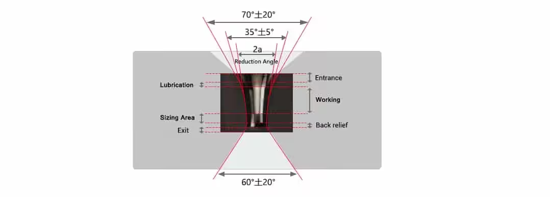
A die is more than a round hole. Inside, it normally has an entrance, a lubrication zone, a reduction zone, a bearing, and an exit. The angle, length, and surface quality of each part shape how the wire deforms.
Too large a reduction angle forces heavy deformation over a short distance, which drives up the drawing force and the internal stress. Too small an angle stretches out the contact length, so friction and heat go up instead. A bearing that runs too long adds friction; one that is too short gives away dimensional stability. That is why the profile has to suit the specific wire material, diameter, area reduction, drawing speed, and lubrication method. One profile for every job does not work.
1.3 Too much reduction in a single pass
Push the area reduction in one pass past what the wire can reasonably take, and the drawing force jumps. If the wire lacks ductility, or its pretreatment was uneven, it will often break near the die exit.
A sound die sequence has to account for:
- wire material and hardness;
- starting and finishing diameters;
- elongation;
- drawing machine power;
- drawing speed;
- die material;
- intermediate annealing;
- lubrication.
In multi-pass drawing, the reduction also has to be spread sensibly across the passes. Overload one pass and you get breakage plus faster wear on that die.
1.4 Poor or missing lubrication
Lubricant does two jobs: it cuts friction between wire and bore, and it carries away the heat of drawing. If a continuous film cannot form on the wire, bare metal touches the bore, and both temperature and drawing force spike.
Typical lubrication faults include:
- wrong lubricant concentration;
- damp, clumped, or degraded drawing powder;
- lubricant fouled by metal particles or oil;
- too little lubricant, or a blocked circulation system;
- poor surface preparation that stops a stable film from forming;
- drawing speeds the lubrication system simply cannot keep up with.
If the wire runs noticeably hotter just before it breaks, or shows discoloration, scoring, or metal pickup, inspect the lubrication and the die cooling.
1.5 Defects in the wire itself
Raw material problems break wire too. Common ones are:
- internal inclusions, segregation, or voids;
- surface laps, cracks, or oxide scale;
- a non-uniform microstructure in the rod;
- incomplete pickling or descaling;
- too much hardness or too little ductility from bad heat treatment;
- weak welds at wire joints.
When breaks happen randomly across different passes and positions, and you find inclusions, cracks, or weld defects near the fracture, look at the raw material and the pretreatment.
1.6 A misaligned die
If the die, guide wheels, capstans, and wire path do not line up, the wire enters the die at an angle. One side of the bore then carries more load, so the wire deforms unevenly and the die wears off-center.
Misalignment tends to cause:
- scratches on one side of the wire;
- eccentric die wear;
- worse roundness;
- swinging drawing tension;
- more breaks.
When you fit a die, get the die box, the wire guides, and the drawing centerline aligned, and check that the die is neither loose nor tilted.
1.7 Unstable speed and tension control
Run the drawing speed too high and frictional heat rises while the lubricant loses its chance to form a protective film. Sharp acceleration, mismatched pass speeds, or unsteady tension can also hit the wire with sudden shock loads.
If breaks cluster at startup, during acceleration, or at spool changes, check:
- the startup ramp;
- the speed ratios between passes;
- the tension sensors;
- the take-up system;
- the capstan surfaces;
- the electrical controls.
2. Reading the cause from where the wire breaks
Where the wire breaks tells you something useful.
Breaks near the die entrance
Likely causes:
- the wire enters at an angle;
- the guide system is off;
- the wire surface has bad defects;
- the entrance is sharp or damaged;
- the wire is vibrating too much.
Breaks in the reduction zone or near the exit
Likely causes:
- too much reduction in one pass;
- a wrong reduction angle;
- a rough or worn bore;
- weak lubrication;
- too high a drawing speed;
- not enough ductility.
Breaks between two dies
Likely causes:
- too much tension between passes;
- damaged capstan or guide-wheel surfaces;
- mismatched speed ratios;
- microcracks left by an earlier pass;
- abnormal machine vibration.
Location alone will not pin down the cause. Read it together with the look of the fracture, the state of the wire surface, the condition of the die, and the process settings.
3. A step-by-step way to work the problem
Slowing the machine down keeps things running for a while, but it does not fix anything. A set procedure works better.
Step 1: Record what happened
Write down:
- which pass broke;
- the time and how often it happens;
- the drawing speed at the break;
- the wire spec and batch number;
- the ID of the die in use;
- the state of the lubricant;
- what the fracture looks like;
- any changes in machine tension and temperature.
Good records tell you whether the trouble is random or tied to a particular material batch, die, or setting.
Step 2: Look at the wire and the fracture
Check the fracture for inclusions, signs of brittle failure, necking, or surface cracks. Look at the wire near the break for scratches, discoloration, burrs, ovality, or a local drop in diameter.
Heavy necking usually means the material stretched a lot before it gave way. A flat fracture with little or no necking points more toward brittleness, an internal defect, or a sudden shock load.
Step 3: Inspect the die
Use a microscope, a profile projector, or other proper measuring gear to check:
- the actual bore diameter;
- the reduction-zone profile;
- the bearing length;
- bore roundness;
- scratches on the inner surface;
- wear rings and eccentric wear;
- cracks or chipping in the insert.
If the die is out of tolerance, or has internal damage that polishing cannot fix, repair or replace it right away.
Step 4: Check lubrication and cooling
Confirm that lubricant concentration, temperature, cleanliness, and supply all meet the process spec. See whether metal particles or deposits have built up in the die box. For high-speed drawing, make sure the cooling system can actually hold the die and the wire at the right temperature.
Step 5: Review the die sequence and settings
Recalculate the area reduction for each pass and find any pass carrying too much. Check that drawing speed, tension, and annealing suit the wire material.
Step 6: Check machine alignment and condition
Make sure the die boxes, guide wheels, capstans, and take-up are positioned correctly. Check bearings, tension devices, and the drive for vibration, runout, or anything else out of the ordinary.
4. Choosing the right die to cut breakage
Die materials differ in hardness, wear resistance, surface quality, impact resistance, and cost. Pick the right one and you get longer die life and steadier drawing.
Nano-coated wire drawing dies use a precision-finished substrate with a nanoscale coating on the working surface. The coating creates a smooth, low-friction bore that helps the wire move through the die more evenly. These dies are well suited to drawing copper, aluminum, stainless steel, and other wires where surface quality, dimensional consistency, and stable production matter.
What they offer:
- lower friction between the wire and the die bore;
- less heat buildup during drawing;
- reduced wire scoring and metal pickup;
- a smoother, cleaner wire surface;
- improved bore wear resistance and dimensional stability;
- longer service life and fewer die changes.
By reducing friction and keeping the bore surface smooth, nano-coated dies can lower drawing resistance and reduce the local stress concentrations that often lead to wire breakage. They are a practical choice for high-speed or continuous production, especially when conventional dies wear too quickly or struggle to maintain a consistent wire finish.
Their performance still depends on the right bore profile, reduction schedule, alignment, lubrication, and coating quality. A nano-coated die cannot compensate for excessive reduction, poor wire material, or unstable machine tension.
PCD dies are hard and hold up well against wear. They suit high-speed, long-run drawing of copper, aluminum, stainless steel, and similar materials.
What they offer:
- long service life;
- a bore that holds its size;
- steady output at high, continuous speeds;
- more consistent wire diameter;
- fewer die changes and less downtime.
For high-volume, continuous work, PCD dies bring the cost per unit down. The catch is that the bore profile and the manufacturing accuracy have to match the actual process. A die can be as wear-resistant as you like and still break wire if the profile is wrong for the job.
Natural diamond dies are extremely hard and polish beautifully. They are the usual choice for fine and ultra-fine wire that needs tight tolerances and a clean surface.
What they offer:
- an excellent surface finish on the wire;
- suitability for small bores and high-precision work;
- favorable friction behavior;
- precise control of fine-wire size.
Because natural diamond has a crystal orientation, making and using these dies calls for professional bore design and tight quality control.
5. Maintenance that keeps breaks from coming back
Steady production comes from managing each die across its whole life.
Keep die records
For every die, log the spec, material, install date, output, number of repairs, and why it was scrapped. Those records let you estimate die life and schedule replacements before a failure forces one.
Inspect bore size and surface on a schedule
Do not wait for repeated breaks to inspect dies. Set an inspection interval based on the wire material and the output so you catch wear rings, bore growth, and eccentric wear early.
Keep dies clean
When production stops, clear metal particles, lubricant residue, and debris from the bore and the die box. Do not use hard or sharp tools that could scratch the inner surface.
Revisit the sequence and reductions
Whenever the wire material, starting diameter, target size, or speed changes, work out the die sequence again rather than reusing the old settings.
Repair or replace worn dies without delay
Minor wear can sometimes be brought back by grinding and polishing. A cracked insert, heavy eccentric wear, or an out-of-tolerance bore, though, means replacement. Keeping a failed die in service just adds more scrap, more downtime, and more breaks.
Conclusion
Frequent wire breakage rarely comes down to one thing. Worn dies, the wrong bore profile, too much reduction per pass, weak lubrication, raw-material defects, misalignment, and unsteady tension can each play a part, directly or indirectly.
The way out is a set troubleshooting routine plus the right die for the wire material, the size, and the speed. Good die materials, a bore profile built for the job, precise inner finishing, and regular maintenance all cut drawing resistance and abnormal wear. That gives you steadier dimensions, a better wire surface, less downtime, and lower cost overall.